
















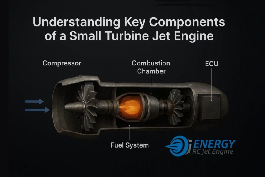
Compressor, Combustion Chamber, Fuel System, and ECU Explained in Depth
Small turbine jet engines—widely used in RC jets, UAVs, and experimental aviation platforms—are marvels of compact engineering. Despite their size, their internal architecture mirrors that of full-scale aviation turbines.
To truly understand performance, reliability, and operational safety, it’s essential to know what’s happening inside.
This article provides a deep, engineering-oriented breakdown of the four most critical subsystems:
The Compressor
The Combustion Chamber
The Fuel Delivery System
The ECU (Electronic Control Unit)
Whether you’re a hobbyist, a UAV developer, or an aerospace engineer, this guide will help you understand how these components work together to deliver stable thrust, efficient combustion, and precise engine control.
1. The Compressor — The Engine’s Breathing System
The compressor is the first major component that incoming air encounters. Its job is simple in concept but complex in execution:
raise the air pressure before it enters the combustion chamber.
How it works
Most small turbine engines use a single-stage radial (centrifugal) compressor.
Air is drawn in through the intake and accelerated outward by a high-speed impeller, increasing both its velocity and pressure. A diffuser then converts the air’s kinetic energy into static pressure.
Why it matters
Higher compressor efficiency directly influences:
Overall thrust output
Specific fuel consumption (SFC)
Temperature margin before turbine overheating
Key engineering considerations
Impeller design (blade geometry, hub-to-tip ratio, surface finish)
Material strength to withstand 80,000–160,000 RPM
Dynamic balance—even micrometer-level imbalance can cause vibration, bearing wear, or catastrophic failure
Clearances between impeller and housing for maximum efficiency
In high-end engines, CNC-machined impellers and multi-axis balancing are critical for consistent performance.
2. The Combustion Chamber — Where Energy is Released
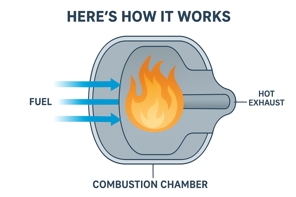
Once air exits the compressor, it enters the combustion chamber, where fuel is atomized and ignited.
Functional purpose
The combustion chamber’s job is to:
Mix compressed air with finely atomized fuel
Sustain a stable, controlled flame
Deliver hot gases to the turbine at uniform flow and temperature
Combustion chamber design in small turbines
Most micro turbine engines use an annular combustor with a vaporizing or pressure-atomizing fuel system.
Engineering challenges
Preventing flameout while maintaining a wide operating envelope
Avoiding hot spots that damage turbine blades
Ensuring uniform fuel–air mixing for clean combustion
Thermal management: the combustor must survive 700–900°C internal temperatures
High-quality engines use carefully designed primary, secondary, and tertiary air zones:
Primary zone: maintains stable flame
Secondary zone: completes combustion
Dilution zone: cools the gases for turbine entry
This balancing act is what separates stable engines from unreliable ones.
Read More:Inside RC Turbine Jet Engines: How Miniature Jet Power Works
3. Fuel System — The Engine’s Lifeline
The fuel system ensures precise delivery and atomization of the fuel—typically kerosene, Jet-A, or Jet-A1.
Main components
A complete micro turbine fuel system usually includes:
Fuel pump (brushless or brushed, ECU-controlled)
Fuel solenoid valve
Fuel filter
Fuel lines
Atomizers/injectors in the combustor
Precision matters
Micro turbine combustion environments are extremely sensitive to:
Fuel flow rate
Atomization quality
Pump response time
Line pressure stability
Even minor variations cause:
Slow throttle response
Flameouts
Excessive exhaust temperatures (EGT)
Premature turbine wear
Closed-loop control
Modern systems measure EGT, RPM, and pressure, adjusting pump output in real time to maintain:
Optimal mixture ratio
Safe turbine temperature
Smooth throttle transitions
This is where the ECU plays a critical role.
4. ECU — The Brain of the Jet Engine
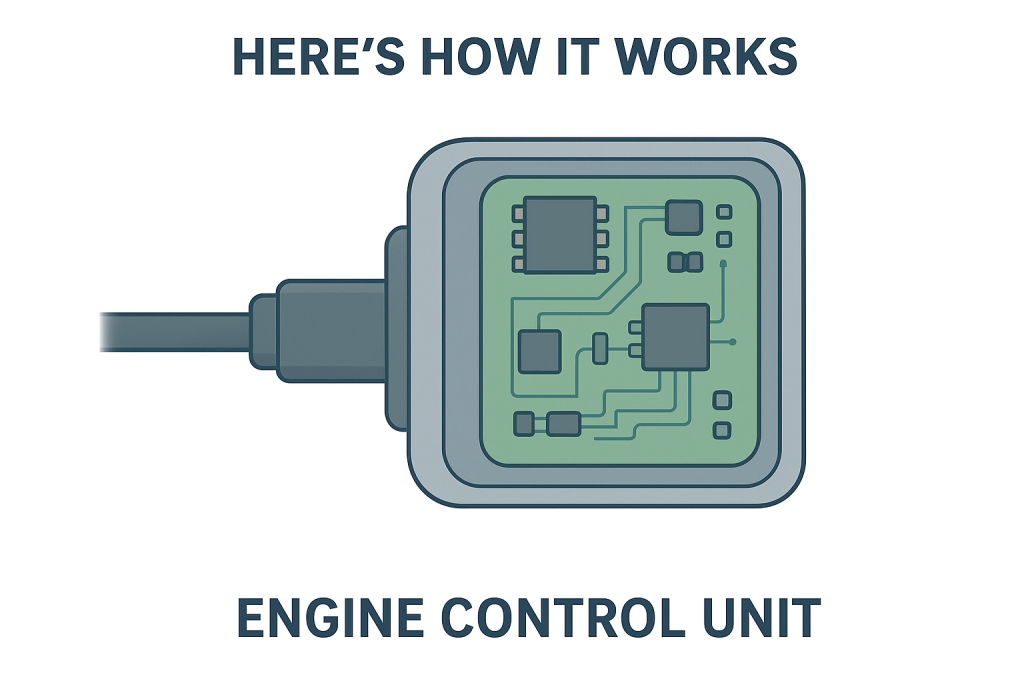
The Electronic Control Unit (ECU) is arguably the most advanced component in a micro turbine system.
It performs what used to require an entire system of mechanical regulators in older full-size jets.
Core responsibilities
The ECU continuously monitors and controls:
RPM (via magnetic or optical sensors)
Exhaust gas temperature (EGT)
Fuel pump power
Starter motor engagement
Glow plug/igniter timing
Acceleration and deceleration limits
It manages the entire engine cycle:
Start sequence
Idle stabilization
Throttle changes
Full thrust operation
Emergency shutdown
Why modern ECUs are so critical
Micro turbines operate at extremely high speeds and temperatures.
A 2–3 second delay in control action can lead to:
Over-temperature turbine damage
Compressor stall
Combustion instability
Mechanical failure
Advanced ECUs use:
PID control algorithms
Redundant safety thresholds
Real-time diagnostics and logs
This enables safe operation even for non-expert pilots or UAV operators.
Learn More:How to Choose the Right RC Turbine Jet Engine (40–150kgf Range)
How These Components Work Together
Although each subsystem has its own function, the engine only works when all four perform in harmony:
Compressor pressurizes air
Fuel system atomizes and meters fuel
Combustion chamber converts chemical energy into hot, high-speed gas
ECU coordinates everything to maintain stable, efficient operation
A micro turbine is essentially a high-energy chain reaction kept under tight electronic and mechanical control.
If one subsystem malfunctions, the entire engine’s reliability is compromised.
Conclusion
Understanding the compressor, combustor, fuel system, and ECU provides deep insight into how small turbine jet engines achieve their remarkable power-to-weight ratio and performance.
For engineers, UAV developers, and high-end RC hobbyists, mastering these fundamentals helps with:
Engine selection
Performance tuning
Troubleshooting
Safe operation